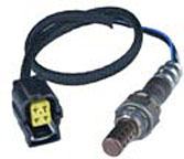
2004 Jeep Grand Cherokee 4.0l Exhaust System Diagram
Welcome to the JeepSpecs.com in-depth page on WJ Generation Jeep Grand Cherokee oxygen sensors. We have organized as much information as we could find into a helpful article below. Is something incorrect or missing? Please get in touch with us and we'll fix it!

Grand Cherokee WJ oxygen sensor
An O2 sensor is a galvanic battery that provides the PCM with a voltage signal (0-1 volt) inversely proportional to the amount of oxygen in the exhaust. In other words, if the oxygen content is low, the voltage output is high; if the oxygen content is high the output voltage is low. The PCM uses this information to adjust injector pulse-width to achieve the 14.7–to–1 air/fuel ratio necessary for proper engine operation and to control emissions.
The O2 sensor must have a source of oxygen from outside of the exhaust stream for comparison. Current O2 sensors receive their fresh oxygen (outside air) supply through the O2 sensor case housing.
Four wires (circuits) are used on each O2 sensor:
- 12–volt feed circuit for the sensor heating element
- Ground circuit for the heater element
- Low-noise sensor return circuit to the PCM
- Input circuit from the sensor back to the PCM to detect sensor operation


Grand Cherokee oxygen sensor locations for 4.0 and 4.7 engines
The Oxygen Sensors (O2S) are attached to, and protrude into the vehicle exhaust system. Depending on the emission package, the vehicle may use a total of either 2 or 4 sensors.
Federal Emissions Package (4.0L and 4.7L engines):
Two sensors are used: upstream (referred to as 1/1) and downstream (referred to as 1/2). With this emission package, the upstream sensor (1/1) is located just before the main catalytic convertor. The downstream sensor (1/2) is located just after the main catalytic convertor.
California Emissions Package (4.0L engine):
On this emissions package, 4 sensors are used: 2 upstream (referred to as 1/1 and 2/1) and 2 downstream (referred to as 1/2 and 2/2). With this emission package, the rear/upper upstream sensor (2/1) is located in the exhaust downpipe just before the rear mini-catalytic convertor. The front/upper upstream sensor (1/1) is located in the exhaust downpipe just before the front mini-catalytic convertor. The rear/lower downstream sensor (2/2) is located in the exhaust downpipe just after the rear mini-catalytic convertor, and before the main catalytic convertor. The front/lower downstream sensor (1/2) is located in the exhaust downpipe just after the front mini-catalytic convertor, and before the main catalytic convertor.
California Emissions Package (4.7L engine):
On this emissions package, 4 sensors are used: 2 upstream (referred to as 1/1 and 2/1) and 2 downstream (referred to as 1/2 and 2/2). With this emission package, the right upstream sensor (2/1) is located in the right exhaust downpipe just before the mini-catalytic convertor. The left upstream sensor (1/1) is located in the left exhaust downpipe just before the mini-catalytic convertor. The right downstream sensor (2/2) is located in the right exhaust downpipe just after the mini-catalytic convertor, and before the main catalytic convertor. The left downstream sensor (1/2) is located in the left exhaust downpipe just after the mini-catalytic convertor, and before the main catalytic convertor
02S Sensor removal
Never apply any type of grease to the oxygen sensor electrical connector, or attempt any soldering of the sensor wiring harness.
WARNING: THE EXHAUST MANIFOLD, EXHAUST PIPES AND CATALYTIC CONVERTER(S) BECOME VERY HOT DURING ENGINE OPERATION. ALLOW ENGINE TO COOL BEFORE REMOVING OXYGEN SENSOR.
1. Raise and support vehicle.
2. Disconnect O2S pigtail harness from main wiring harness.
3. If equipped, disconnect sensor wire harness mounting clips from engine or body.
CAUTION: When disconnecting sensor electrical connector, do not pull directly on wire going into sensor.
4. Remove O2S sensor with an oxygen sensor removal and installation tool.
02S Sensor installation
Threads of new oxygen sensors are factory coated with anti-seize compound to aid in removal. DO NOT add any additional anti-seize compound to threads of a new oxygen sensor.
1. Install O2S sensor. Tighten to 22 ft. lbs. (30 N·m) torque.
2. Connect O2S sensor wire connector to main wiring harness.
3. If equipped, connect sensor wire harness mounting clips to engine or body. When Equipped: The O2S pigtail harness must be clipped and/or bolted back to their original positions on engine or body to prevent mechanical damage to wiring.
Grand Cherokee WJ oxygen sensors(Part Numbers: Black text = Federal emissions, Black + red text = California emissions) | |||||
| Engine | Before catalyst | After catalyst | |||
1999-2000 | |||||
| 4.0L | 56041676AA (w/10.5″ pigtail) 56041212AE (w/18″ pigtail) | 56041344AD (w/14″ pigtail) 56041212AF (w/12″ pigtail) | |||
| 4.7L | 56028233AA (w/12″ pigtail) 56028232AA (w/18″ pigtail) | 56041345AD (w/14″ pigtail) 56028235AA (w/12″ pigtail) | |||
2001-2003 | |||||
| 4.0L | 56041943AA 56041944AA | 56041845AB 5139020AA | |||
| 4.7L | 56029333AA 56041941AA | 56041345AE 56041731AA | |||
2004 | |||||
| 4.0L | 56028995AA 56028994AA | 56028997AA 05139021AA | |||
| 4.7L | 56044580AA 56044581AA | 56044582AA 56044583AA | |||
Posted by: aubreygirvine0197813.blogspot.com
Source: https://jeepspecs.com/wj-generation/wj-jeep-parts-equipment/02s-oxygen-sensor-guide/
Post a Comment for "2004 Jeep Grand Cherokee 4.0l Exhaust System Diagram"